Description
⏳ Build your time, master your craft — the clock that ticks with your skills!
- SLEEK DIY DESIGN - Transparent acrylic shell doubles as a modern desktop art piece, blending tech with style.
- HANDS ON STEM MASTERY - Ideal for students and DIYers to sharpen soldering skills and deepen electronics knowledge.
- ADAPTIVE BRIGHTNESS CONTROL - Auto or manual LED brightness adjustment ensures perfect visibility anytime, anywhere.
- PRECISION MEETS PRACTICALITY - Accurately displays time, date, and temperature in real time for seamless daily use.
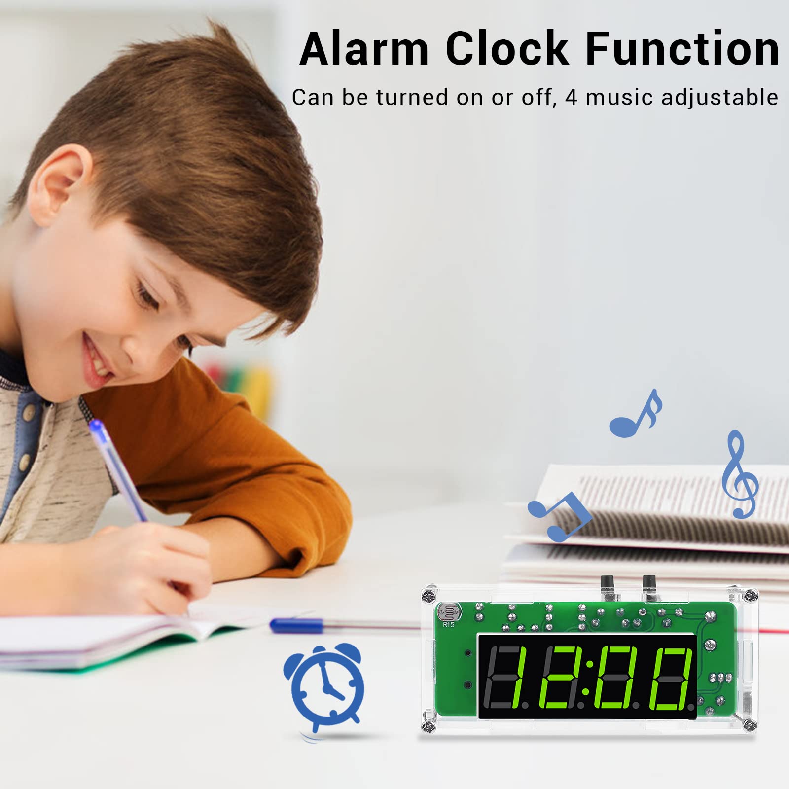
- CUSTOMIZABLE ALARM EXPERIENCE - Choose from 4 distinct alarm melodies to personalize your wake-up routine.
The MiOYOOW TJ-56-428 is a 4-digit digital clock kit featuring a light-controlled LED display that shows time, date, and temperature. Designed for DIY enthusiasts and students, it offers adjustable brightness, 4 alarm melodies, and power-off memory. This soldering practice kit combines hands-on electronics learning with stylish acrylic casing, making it perfect for STEM education and desktop décor.